CHIIP: Wireless Structural Health Monitoring
A structural health monitoring device for earthquakes, taken from 9 microcontrollers down to a single ESP32 at 85% less per unit. My senior project.
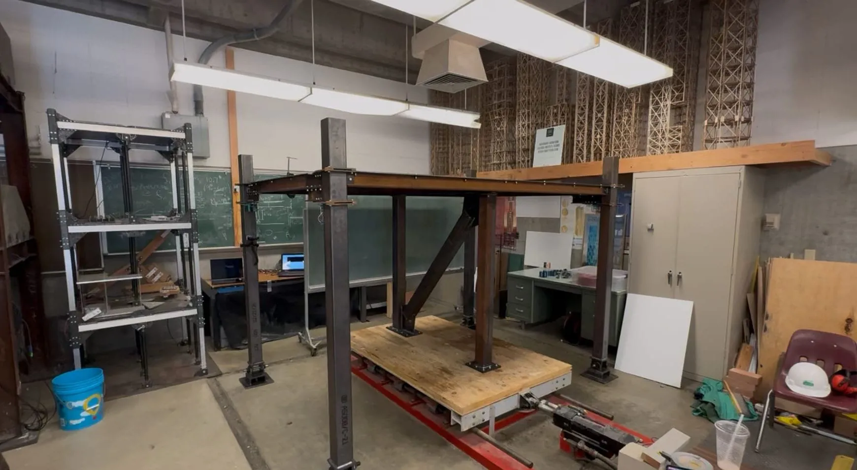
On large-scale structural projects like the Burj Khalifa, millions of dollars are spent on reliable structural health monitoring (SHM) devices to monitor the building’s movement and safety. But what if they didn’t have to be this expensive?
SHM is exactly what it says: a device to monitor the health of a structure, in this case during seismic activity, aka earthquakes. Building collapses during earthquakes kill tens of thousands of people per year, so ensuring the safety of a building is critical to protect human lives. During the construction of a new building, how do you know it’s safe? After an earthquake, with the building still standing and no visible damage, should it be evacuated? Is the integrity of the building compromised?
There are already many devices that can provide this functionality. But nothing exists that combines all the sensors used in a structural health monitoring device into one affordable solution. This project takes the functionality of most SHM devices on the market and boils it down to its bare necessities, to make it affordable and more accessible.
The problem
CHIIP (Continuous Health Information for Infrastructure Protection) started as a rough prototype from earlier work by Cal Poly students. My job was to turn it into a less rough prototype: revamp the firmware, the web server and the overall design. My main goal was to simplify the embedded system, decrease the cost per unit, remove as many points of failure as possible and shrink the physical footprint, while still providing the same functionality and data.
The original design had 6 different sensors, providing 10 streams of analog data, connected to 9 different microcontrollers: 4 Arduino Portenta H7s and 5 ESP32s.
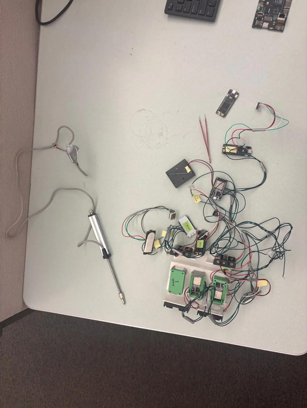 CHIIP V1, before deconstruction.
As many projects do, the scope changed over time. But the general goals were:
- Take the device from 9 microcontrollers to just 1, while still providing the same functionality.
- Build 4 of these devices that sync their data and capture data simultaneously.
- Overhaul the web server to show the 4 devices working together, and individually.
Stage one: learning what I was doing
The first stage was about initial testing, learning about what I was doing, tinkering with the components and sensors, and tearing apart the old version of the device to harvest it for parts. I learned how to program the sensors, how to solder, how to get data from a microcontroller to a PC over USB, and how to collect multiple streams of analog data and build a JSON from it. Over the course of this project my soldering got much faster, and much better.
The sensors are an accelerometer, inclinometers, a strain gauge and a linear potentiometer. All of them output a voltage from 0 to 3.3 V, and their measurements are calculated from that range. The linear potentiometer, for instance, is a metal rod that reads 0 V fully extended and 3.3 V fully retracted.
Instead of working with the old web server, I thought it would be easier to recreate it from scratch: a table of the latest data points, real-time graphs, a button to start and stop a recording, and a button to download the recording as a CSV file.
Stage two: the right tool for the job
The second stage was where the bulk of the design happened: how to shrink a 9-microcontroller device down to a single one, how to make it wireless, and what the “best” tool for the job would be. Best meaning the most simple and cost-effective solution that has everything we need, and nothing more.
The original work was done on the Arduino Portenta H7 with a breakout board to expose all the analog pins. That ended up being very overkill for our use case, and very expensive. The Portenta has a powerful processor meant for heavier tasks like small machine learning models and computer vision. After working with it for a couple of months, I realized I was using the wrong tool for the job. What I wanted was an ESP32 with enough analog pins. Good news for me: the architectural engineering students already had a ton of ESP32 dev kits lying around from earlier work on the project.
At first I thought we were golden. There were 6 analog pins on ADC1 and 9 on ADC2, plenty for 10 streams of data. Then I ran into one problem: the Wi-Fi chip shares the same channel as the ADC2 pins, so you can’t use Wi-Fi and ADC2 at the same time. I tried quickly turning Wi-Fi off, reading ADC2, and turning it back on, but the microcontroller couldn’t reconnect fast enough to send the data.
The fix came from meeting with the architectural engineers. Together we removed redundancy and anything that wasn’t necessary: one of the strain gauges, the Y-axis of the inclinometer and the Z-axis of the accelerometer. That left exactly 6 streams of data, exactly as many ADC1 pins as the ESP32 has.
Going wireless brought another problem. Sending JSONs at 15 Hz over USB is much easier than sending them at 15 Hz over Wi-Fi, which means 15 separate messages to the web server per second. So I batched the data: 1 message per second containing 15 data points, rather than 15 messages each containing 1.
Then I found that HTTP POST requests take a long time, on the order of 100 to 800 ms, which left half-second holes in the data and made it unusable for analysis. To remove them, I used both cores of the processor in a producer-consumer model. The producer core samples the sensors and converts the readings; the consumer core batches them and sends them over Wi-Fi.
Stage three: four devices, on their own
The last stage was building 4 devices, getting them all to work together and stay synchronized on the web server, and figuring out how to power them. This meant many hours at the soldering iron in the Engineering East lab, clipping and stripping wires, and testing.
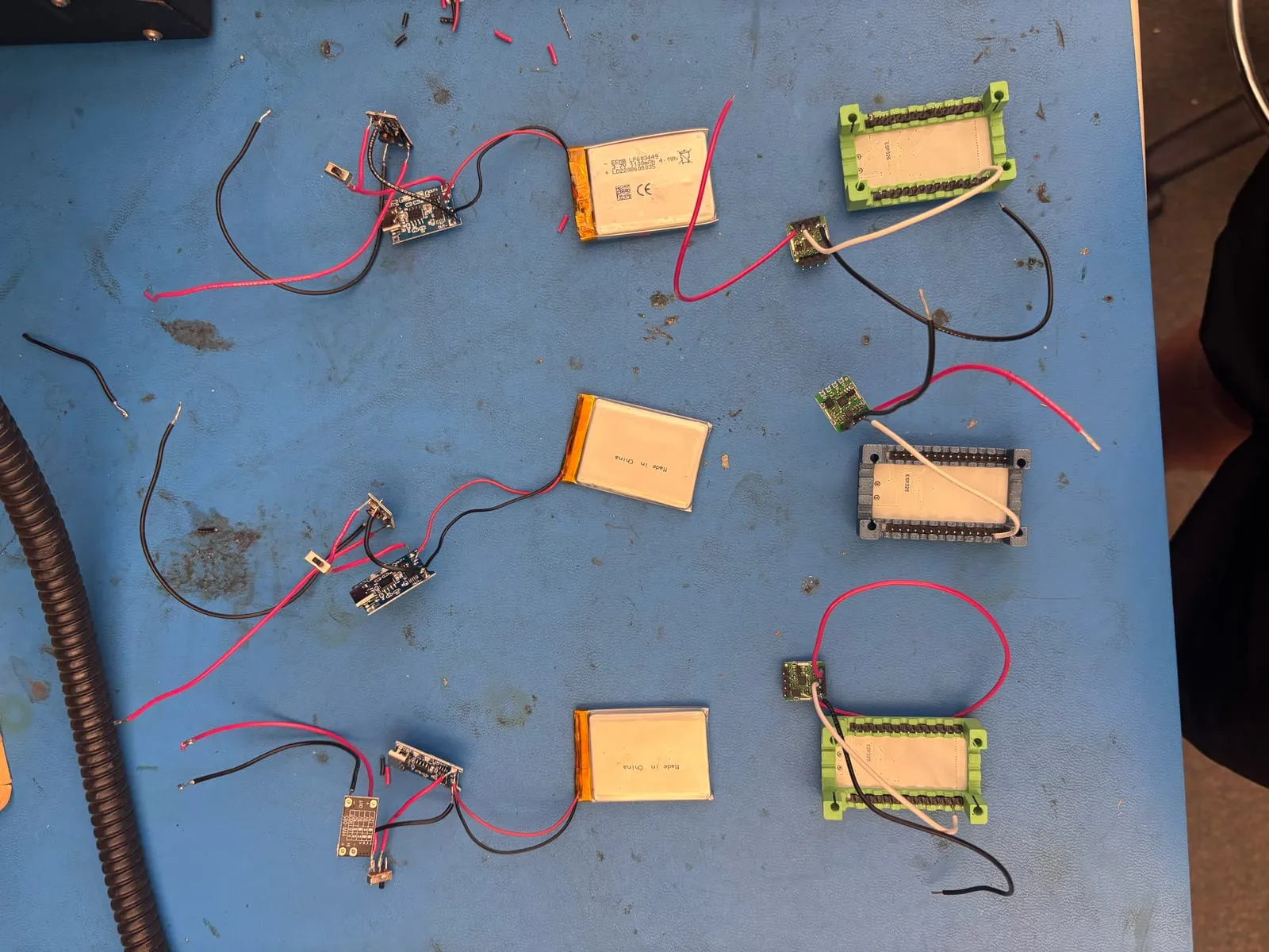 The battery packs in progress.
From the beginning, the microcontrollers had been powered from my laptop. Once four of them are strapped onto a massive steel structure that’s shaking around, they need to power themselves. Each one runs on a 3.7 V lithium-ion battery soldered to a boost converter that takes it up to 5 V for the ESP32, plus a TP4056 charging module so the batteries can be recharged, and a small switch to turn the device off and save battery (and prevent a fire hazard). I had never worked with batteries like this before, so I found it really interesting.
The devices also needed timestamps that mean something relative to each other. When each ESP32 boots, it pings a global atomic clock (pool.ntp.org) to sync its internal clock with real time. As the producer core samples at 15 Hz, it stamps each data point at the exact moment the physical event occurred, inside the JSON, before it ever reaches the server. Wi-Fi latency no longer matters, and the four devices are synchronized.
On the website, I added tabs to view one node at a time or all four together, and a last-minute taring feature that zeros out the sensors once they’re attached to the building.
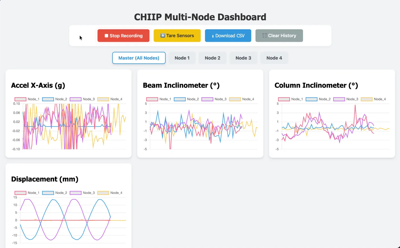 The dashboard during final testing, with all four devices connected.
On the shake table
The whole purpose of the project was this round of testing: four devices on a model structure attached to a giant shake table, collecting data for the architectural engineers. The large-scale testing was a success, and we captured all of the data of the structure being shaken around.
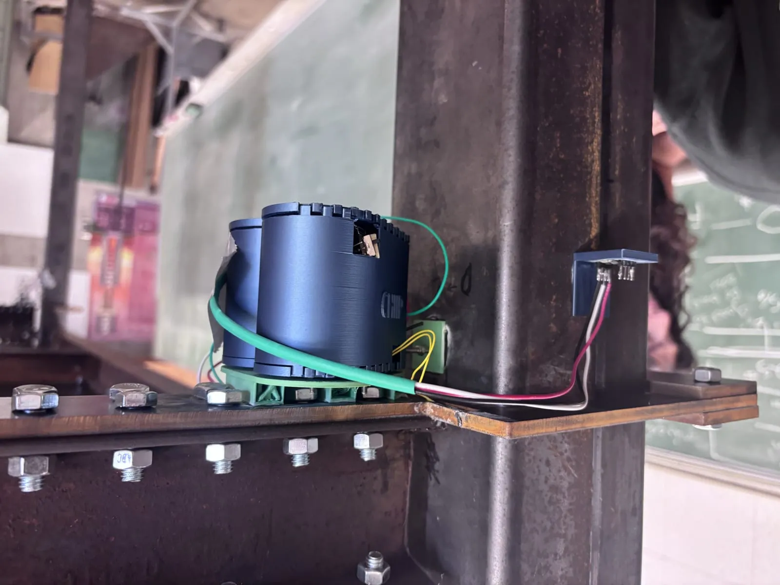 CHIIP V3 on a steel beam-column joint.
It’s hard to quantify success beyond “it did what it was supposed to,” so here are the numbers. Replacing four Portenta H7s at $114 each (and eight of the nine microcontrollers overall) with a single $6 ESP32 took the per-unit cost from $586 to $87, an 85% reduction.
| Microcontrollers | Cost per unit | |
|---|---|---|
| CHIIP V1 (original) | 4 Portenta H7 + 5 ESP32 | $586 |
| V2 (my first prototype) | 1 Portenta H7 + breakout board | $264 |
| V3 (final) | 1 ESP32 | $87 |
Small-quantity prices from April 2026, not counting batteries, wire and solder.
The simplification also reduces the points of failure, and makes the design more robust and much easier to replicate.
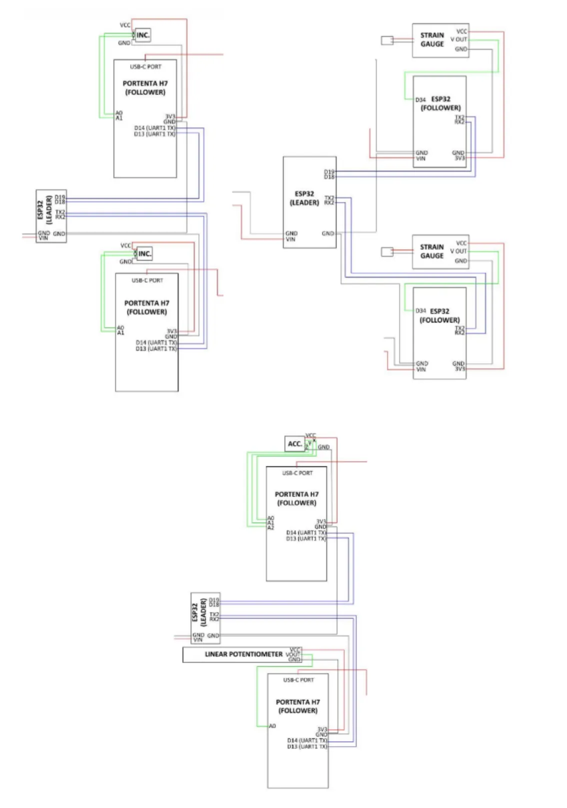 Before: the original CHIIP hardware.
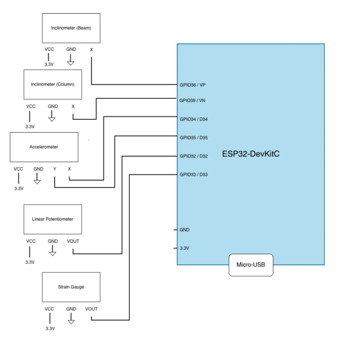 After: every sensor on one ESP32.
Where it could go next
- A custom PCB with the sensors, power and charging on one board. It would cut cost further, perhaps another order of magnitude in mass manufacturing, make the device smaller, and make it more reliable than hand-done “artisan” solder joints.
- On-device storage. Earthquakes take out power, and with it the internet. Just as planes have black boxes, buildings could too: if a building collapses, its data could help us understand what happened and engineer safer buildings in the future.
- Wake on motion. The ESP32’s lesser-known third processor, the Ultra-Low-Power coprocessor, could watch the accelerometer and wake the whole system when an earthquake starts, so the batteries last far longer. The hard part is deciding what counts as an earthquake. Do you care about a magnitude 0.2? Probably not. An 8.7? Most definitely.
Looking back
CHIIP V3 took the proof of concept from an initial prototype and made it more robust, efficient and effective. It was also great practice in interdisciplinary collaboration: I got to work with architectural engineering students to meet the requirements for an embedded systems design, and to bring a cheap alternative to the structural health monitoring space.
I used AI tools (Gemini and Claude) throughout. As a computer engineering student with no background in web development, I found them especially useful for building a full web app with Flask and a SQLite database, and for understanding the existing firmware line by line. Without them, I believe this project’s scope would have been for 2 or 3 students rather than just me.